Mastering the Invisible: The Evolution and Impact of Vortex Control Technologies in Modern Aviation
Commercial aviation is a game of margins. Airlines operate in a cost environment where even fractional efficiency gains matter. Among all operational expenses, fuel remains one of the most volatile and decisive. That is why aerodynamic efficiency is not just an engineering concern it is a strategic priority.
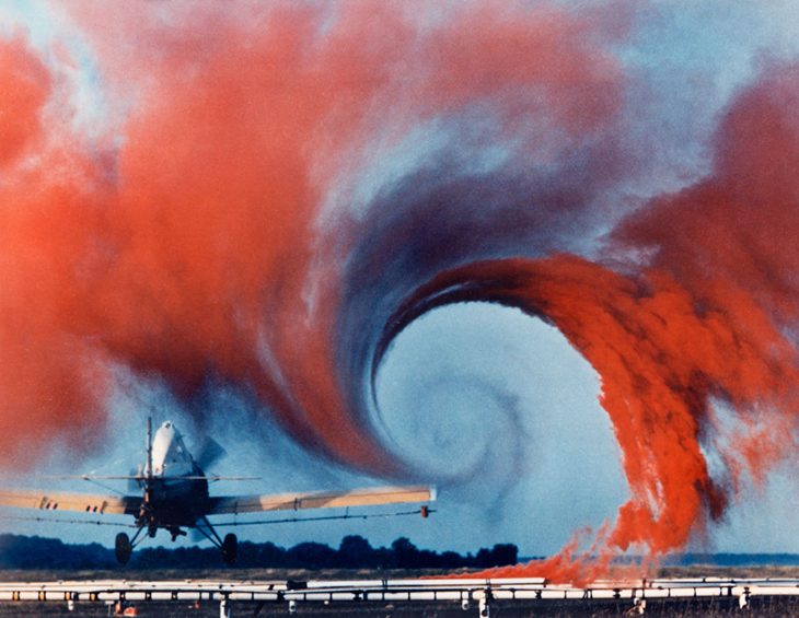
Every aircraft moving through the air generates vortices. These swirling air structures are not design flaws; they are a natural consequence of producing lift. However, if unmanaged, they increase drag, reduce efficiency, and limit performance. Vortex Control Technologies (VCT) focus on understanding and shaping these airflow patterns to improve performance, safety, and fuel economy.
The Physics of the Problem: Drag and Separation
To understand the necessity of vortex control, one must first understand the two enemies of efficient flight: induced drag and flow separation.
Induced drag is the aerodynamic penalty paid for lift. As a wing generates lift, the air pressure below the wing is higher than the pressure above it. At the wingtips, this high-pressure air seeks to equalize by curling around the tip to the low-pressure upper surface. This creates a lateral flow that results in a powerful, spinning vortex trailing behind the aircraft. These wingtip vortices deflect the airflow behind the wing downward (downwash), effectively tilting the lift vector backward and creating a retarding force known as induced drag.
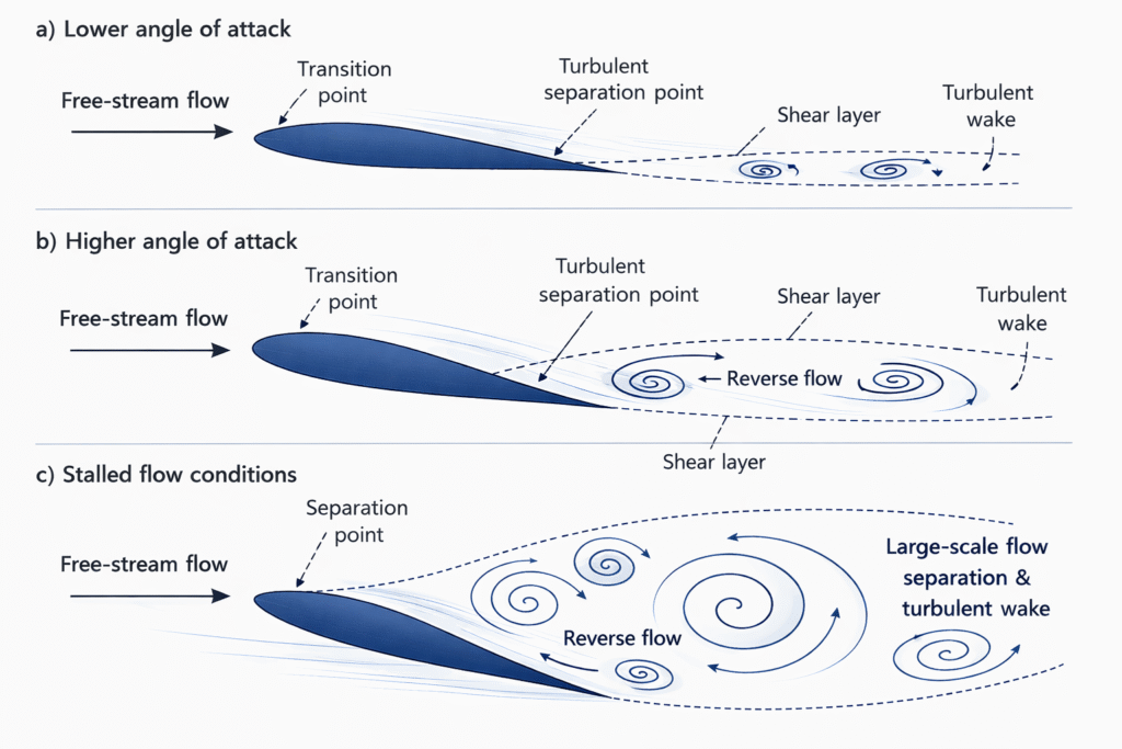
Flow separation, on the other hand, concerns the “boundary layer”—the thin sheet of air sticking to the aircraft’s skin. As air flows over curved surfaces, such as the aft fuselage or a steeply angled wing, friction robs the air of energy. If the air slows too much, it detaches from the surface. This separation creates a turbulent, low-pressure wake that sucks the aircraft backward, a phenomenon known as pressure drag.
Wingtip Devices: Taming the Tornado
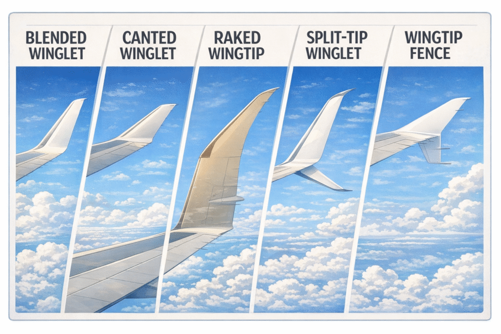
The most visible vortex control solution is the winglet. Developed and refined in the 1970s, winglets reduce the strength of wingtip vortices by limiting the pressure-driven airflow around the wingtip.
Over time, several configurations have emerged:
- Canted Winglets
Seen on aircraft such as the Boeing 747-400, these angled surfaces delivered fuel savings of approximately 3–4%. - Blended Winglets
Featuring a smooth transition at the wingtip, blended winglets reduce interference drag and became widely adopted on Boeing 737NG aircraft. - Split Scimitar Winglets
Adding a ventral strake beneath the wingtip, this design further refines vortex management. Operators have reported roughly 2% additional fuel savings over earlier blended configurations. - Raked Wingtips
Used on aircraft such as the Boeing 777 and 787, raked wingtips extend and sweep the wing rather than adding vertical structures. This increases effective aspect ratio and reduces vortex intensity without the structural weight of upright winglets.
Each iteration reflects the same principle: small geometric refinements can produce measurable operational gains.
Surface Flow Control: The Role of Vortex Generators
While winglets fight large vortices, Vortex Generators (VGs) are designed to create small, beneficial ones. VGs are small vanes, usually an inch or two high, placed in rows on wings and tail surfaces.
Their function is counter-intuitive: they deliberately create turbulence. By generating tiny, high-energy vortices, VGs act as “mixers.” They pull fast-moving free-stream air down into the sluggish boundary layer near the aircraft skin. This re-energizes the boundary layer, allowing it to stay attached to the wing surface at higher angles of attack and slower speeds.
For commercial airliners, VGs are critical safety devices. They are often found near ailerons and rudders to ensure these control surfaces remain effective during landing approaches. Without them, the airflow over the controls might separate, leaving the pilot with “mushy” or unresponsive controls at critical moments (Anderson, 2017).
Aft-Body Flow Control: The “Finlet” Revolution
A specific area of focus in recent years has been the rear fuselage of transport aircraft. Aircraft like the Boeing C-17 Globemaster III, C-130 Hercules, and even the Boeing 737 have an upswept rear section (often called a “beavertail” or “aft-body”). As air flows over this curvature, it tends to separate, creating a massive wake of “dead air” that drags the plane backward.
Companies such as Vortex Control Technologies (VCT) have developed “Finlets”—arrays of small strakes placed on the aft fuselage. Unlike VGs which are for stall protection, Finlets are purely for drag reduction. They generate organized vortices that scour the aft fuselage, keeping the airflow attached further down the tail cone.
For operators like Avelo Airlines, which installed Finlet systems on their Boeing 737-800 fleet, the results are measurable. The system reduces the pressure drag at the rear of the plane, resulting in a fuel reduction of roughly 1.4% and extended range. While 1.4% may seem small, for an airline spending millions on jet fuel, the Return on Investment (ROI) is achieved rapidly (Aerospace Global News, 2023).
Nacelle Chines: Protecting the Wing
Another vital VCT application is the nacelle chine (or strake). Modern high-bypass turbofan engines are massive and mounted close to the wing. At high angles of attack (during takeoff), the sheer size of the engine housing (nacelle) can block airflow over the wing, causing the area behind the engine to stall prematurely.
To prevent this, a small fin is welded to the side of the engine nacelle. This chine generates a powerful vortex that streams over the top of the wing. This vortex acts as a fluid barrier, energizing the flow and ensuring the wing continues to generate lift even at steep climb angles. This allows for lower takeoff speeds and shorter runway requirements.
Conclusion
Vortex control technologies demonstrate that efficiency gains in aviation often come from understanding subtle aerodynamic behaviors rather than relying solely on larger engines or structural redesigns. From winglets to vortex generators, finlets to nacelle chines, each solution reflects a deeper insight into airflow physics. By managing the invisible forces that shape flight, the industry continues to advance both economic and environmental performance. In aviation, precision in airflow management is not just an engineering achievement it is a competitive advantage.
References
Aerospace Global News. (2023). Avelo employs emission-reducing technology. Retrieved November 23, 2025, from https://aerospaceglobalnews.com/news/avelo-employs-emission-reducing-technology/
Anderson, J. D. (2017). Fundamentals of Aerodynamics (6th ed.). McGraw-Hill Education.
Boeing. (2014). Split Scimitar Winglets. Boeing Commercial Airplanes.
NASA. (2008, August 18). Blended Winglets. National Aeronautics and Space Administration. https://www.nasa.gov/wp-content/uploads/2022/03/nasa_rsf_2022.9.30_final.pdf
NASA Langley Research Center. (1990, May 4). Wake vortex study at Wallops Island [Photograph]. NASA Image and Video Library. https://commons.wikimedia.org/wiki/File:Airplane_vortex_edit.jpg